AC Motor Controller
A system to control three-phase AC induction motors in EV applications
Introduction
I’ve always had an interest in electric vehicles (EVs) and motors in general, which probably has something to do with my passion for cars and driving coupled with my innate desire for efficiency (hence, the engineering degree). Therefore, when it came time to develop a system for my capstone project during my degree, the idea of creating a motor control system for an EV immediately came to mind.
Developing an AC motor control system offered me exposure to many interesting challenges including developing and debugging real-time microcontroller applications, generating precise three-phase PWM waveforms and designing power electronics precisely switching hundreds of amps. It also presented the possibility of turning an IGBT into a shower of sparks and flames, which is always fun.
Initial Design Choices
I had already decided that I wanted to develop an AC system, and designing it to handle three-phase motors gave the flexibility of using one, two (do these even exist?) or three-phase motors. As for motor selection, I decided to utilize a conventional three-phase, squirrel-cage induction motor (ACIM). These are the most prevalent type of motor in use in industry and offer many advantages over a brushed DC system (which is the prevailing technology for hobbyist EV conversions):
Durability
- A squirrel-cage induction motor has no brushes or slip-rings to wear out
- The motor currents are switched electronically instead of commutated mechanically over brushes, which can cause arcing and other issues at high RPMs or power levels
Motor Availability
- ACIMs can be found easily and for relatively cheap from industrial surplus and the likes
Controller Complexity
- A motor controller for a DC motor can be constructed using a 555 timer, driver IC and switching FET – not very exciting
- To engage myself in a challenging project, I chose to design a system with three-phase outputs, requiring accurate firmware timing and more complex control algorithms (ok so these two points aren’t advantages, just a bonus for me 🙂 )
The disadvantages are typically the increased controller complexity and higher voltage supply required – since most industrial AC motors are wound for voltages in the 240 – 480V range, this means either rewinding the motor for a lower operating voltage or carrying a high voltage battery pack is necessary.
Control Algorithm
For precise torque control and a gasoline engine-like throttle response “feel,” I decided that field-oriented vector control (FOC) would be the desired control method. TI has a relatively succinct and helpful description of the method here: https://www.tij.co.jp/jp/lit/an/bpra073/bpra073.pdf. Put simply, the control scheme involves measuring the phase currents and rotational speed of the motor then using some mathematical transforms to determine the in-phase and quadrature components of the current. With these This all needs to happen real-time, generally requiring a bit of horsepower from the microcontroller.
However, as is often the case with university projects, time constraints prevailed and the FOC control method was shelved for a simple V/Hz (linear voltage to speed control) implementation for hardware verification.
Hardware Design
The project hardware requirements include a microcontroller capable of performing high speed calculations for updating and driving the three-phase PWM signals, a serial (or wireless in this case) communication port for programming and diagnostics, power electronics and drivers for switching the motor currents, feedback circuitry for phase current measurement, as well as protection for over-current and other fault events.
Schematics and gerbers are available at the bottom of the page.
Microcontroller
I decided to design the electronics portion around a relatively powerful microcontroller that would offload most of the critical PWM timing generation to dedicated hardware. The NXP LPC1769 offered a 3-phase motor PWM peripheral as well as a 32-bit architecture running at 120 MHz, with many available libraries and examples for using the peripherals. Programming is straightforward and takes place over the UART.
Programming and Communications
For programming and communication with a host PC during use, I added a SIP UART port to the PCB and used a cheap Bluetooth serial adapter. This lets me program the system without needing a cable from my laptop to the board and monitor the debug output of the system using my Android phone and a Bluetooth terminal app. It’a amazing how cheap these things are these days, I remember finding similar solutions for ~$50 maybe 5 years ago. Now you can buy an adapter from places like DealXtreme for less than $10 shipped! I ended up using the JY-MCU adapter.
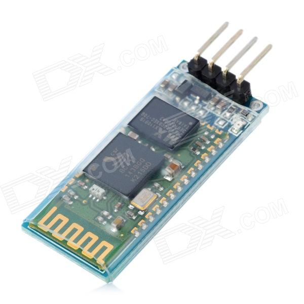 JY-MCU Bluetooth Adapter
IGBTs and Drivers
The driver section consists of six identical circuits; a high and low side driver for each of the three motor phases. Each driver has an independent set of +15.0V and -8.2V rails, provided by an integrated power supply module discussed in the power supplies section below. By using isolated supplies for each driver, each IGBT can be switched with a low-side driver configuration (no need for bootstrapping to generate higher voltages for the high-sides, as each driver circuit is referenced to an IGBT’s emitter). The emitter of each IGBT is tied to the local ground for each driver circuit, and the +15.0V and -8.2V supplies are used to switch the IGBT on and off hard by rapidly charging/discharging the gate. The driver IC selected is a Micrel MIC4451, a 12A low-side driver. This gives plenty of drive current to scale up to larger IGBT packs in the future if desired.
The IGBT pack and motor selected are just for initial testing. Eventually they will be replaced by three 600V 300A dual modules and a hopefully a motor around the 20-30 kW range. The current pack is a FUJI 6MBI100L-060: a 600V, 100A 6-pack IGBT module.
Current Sensors
For most three-phase motor control applications, as well as for safety, current sensors on at least two of the motor phases are necessary. I chose to employ a current sensor on each motor phase, for a total of three sensors, to allow the detection of a short-circuit to ground scenario. The current sensors chosen were the LEM HAL-300S current sensors. These are open-loop hall sensors and can be found for about $30 each on eBay.
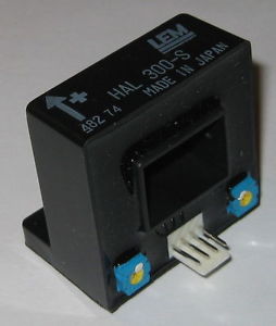 LEM HAL-300
Power Supplies
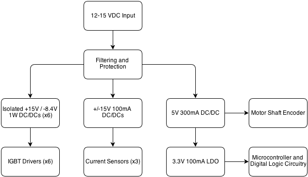 Power Supply Topology
The digital side of the PCB requires a total of four regulated power supplies:
- +5.0V for the motor encoder
- +3.3V for the microcontroller and supporting circuitry
- +15.0V for current sensors
- -15.0V for current sensors
The +5.0V supply is generated with a 78xx pin-compatible switching regulator, the Recom R-78E5.0-0.5. These things are fairly robust and accept 7-28V, with an output current rating of 500mA (limited to 300mA due to input filter inductor current rating). The main draw on this rail is the motor encoder, which is typically ~200mA or so. This supply also feeds the digital supply (+3.3V).
The +3.3V supply is generated with a simple linear regulator fed off of the +5.0V supply. I chose the NCP1117 as it was a common part with minimal requirements for external components. The current requirement on this rail is pretty minimal, mainly just the microcontroller and opto-couplers.
The +/- 15.0V supplies are generated using NCP3063-based switching regulators – newer parts based off of the venerable MC34063. The +15.0V is generated using a boost topology regulator and the -15.0V with a buck-boost regulator.
The six isolated driver sections of the PCB have their own isolated DC/DC converters to provide +15.0V and -8.2V rails used to drive the IGBTs on and off quickly. I chose an off-the-shelf part for this power supply for a couple different reasons, but mainly because I wanted good noise isolation between the high power section and low-voltage digital logic and it would have likely taken more time to develop my own solution than I’d care to spend on a power supply. The part I ended up using is the Powerex VLA106-15242:
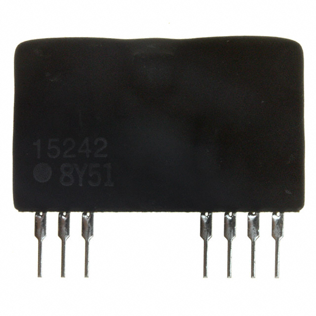 Powerex Isolated +15.0/8.2V DC/DC Supply
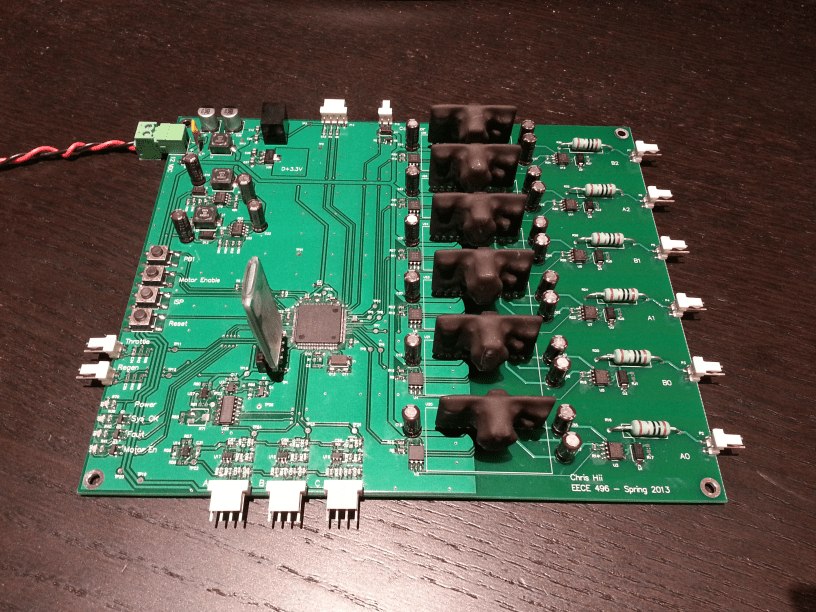
PCB
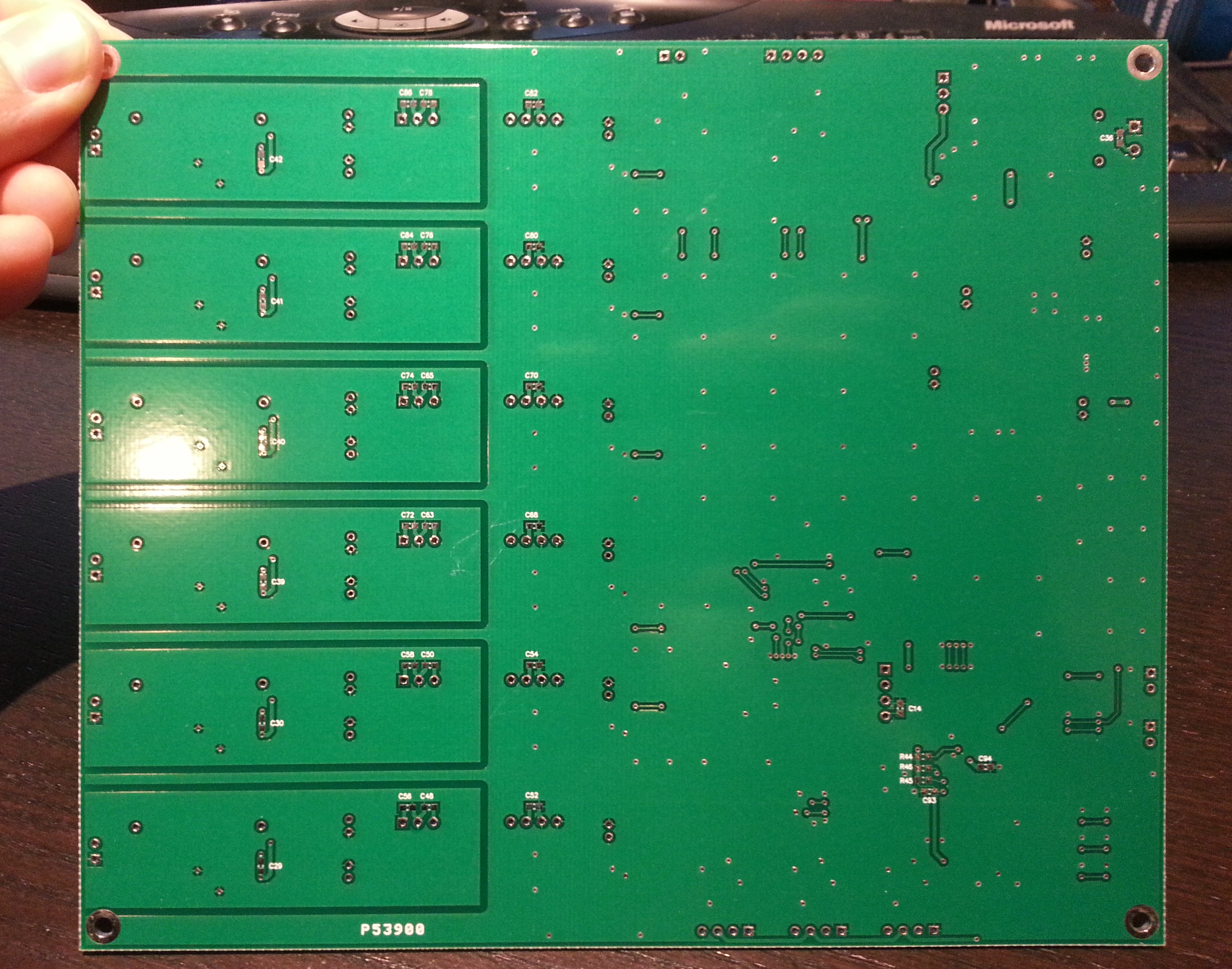
The first revision of the PCB is complete and contains all the control and driver circuitry. It only supports basic functionality and will eventually be replaced with another board with more protection. The board is a 2-layer design sized at 7.00" x 5.85". It could be shrunk down significantly but the fab house I’m using wouldn’t charge less so I left it fairly large. I may choose to separate the driver and control boards in the future but for the first revision I kept it all together. Protection-wise there is over-current protection both in software and hardware but no over-temp, over-voltage, etc. as of this revision.
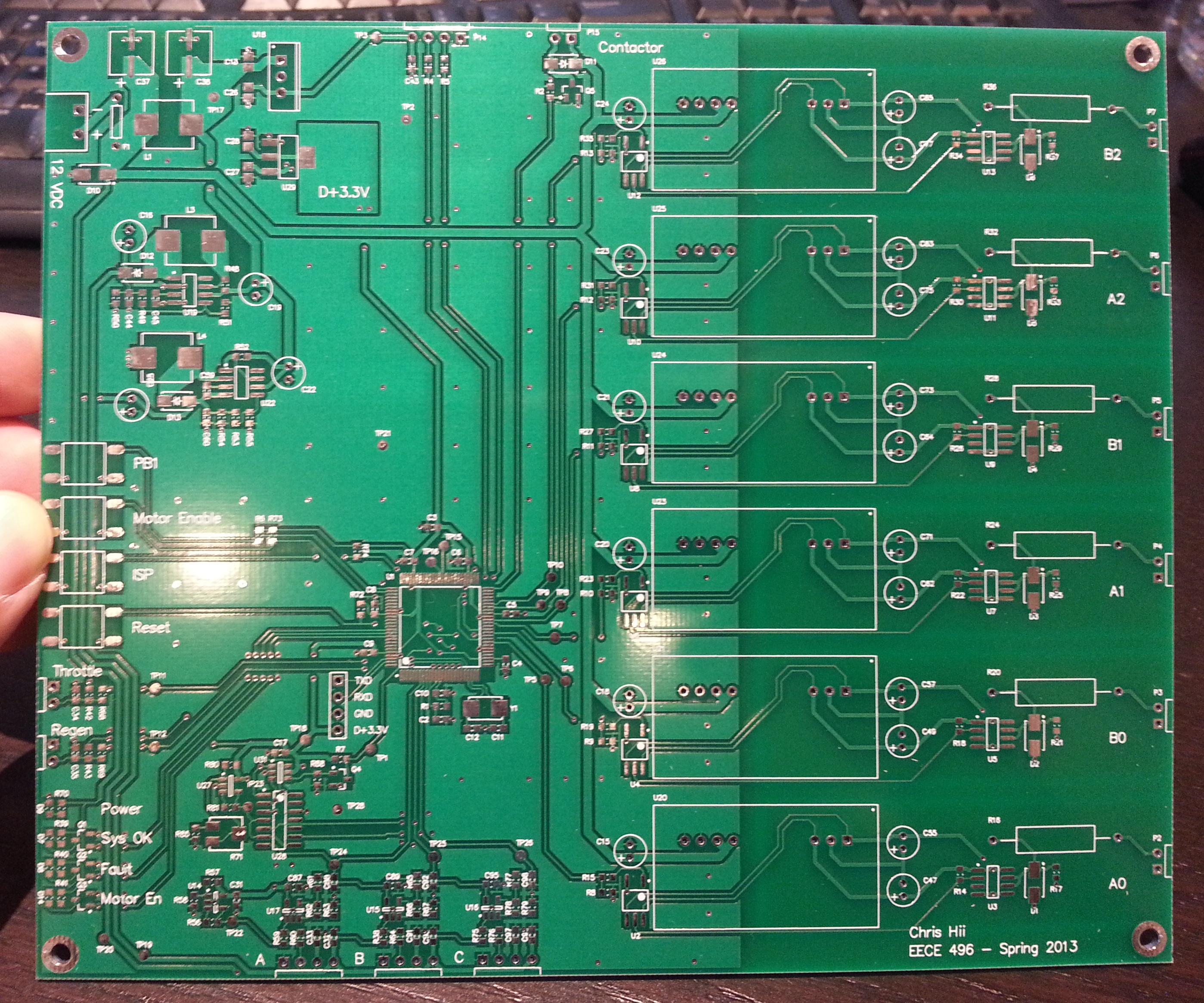 PCB Front Side
Firmware
The requirements for the firmware were as follows:
- Some form of state machine to control the basic operation mode of the motor (stop, forward movement, reverse movement, regen, etc.)
- Precise timing generation for the three-phase motor PWM depending on the speed setting
- Protection from over-current conditions
As for the first project I’ve documented on this site, I will let the firmware speak for itself and attach it at the bottom of the page shortly; some cleanup is required for clarity before publishing.
Results
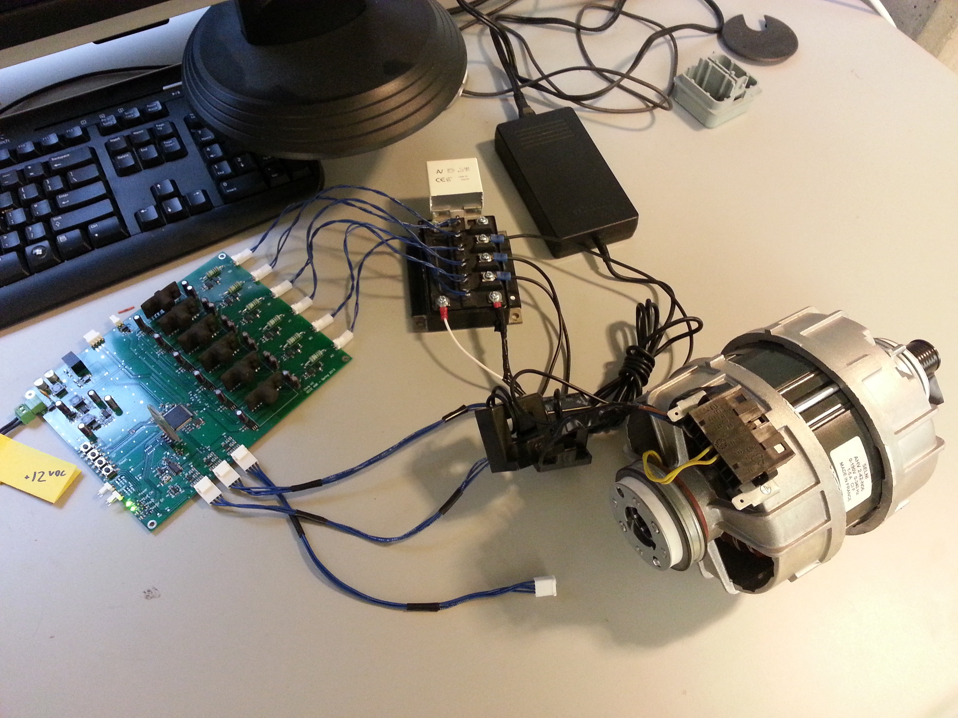 Prototype Test Setup
The system was tested using a laptop power supply (15V, 4A) and a Selni appliance motor (three-phase, 0-400 Hz) intended for use in a washing machine. The motor spins up nicely with good torque and minimal switching noise once above about 10 Hz. Adjustable over-current protection is implemented and is tested to work well.
Due to time constraints (essentially 3 months for everything from project conception to functional prototype), I was not able to implement the full vector torque control. The code is largely written, but untested and likely in need of substantial more effort to implement. The system currently works on a simple V/Hz control algorithm (applied voltage increases linearly with motor frequency) with no feedback.
For more pictures and a write-up that sounds distinctly like a university final report, see the link below in the design files section.
Summary
A three-phase AC motor controller system was developed from concept to functional prototype. Hardware and firmware were produced and a scalable, modular system was created. The system was tested at low power levels to work well and is ready to begin testing at higher power levels. The V/Hz control algorithm allowed for verification of the hardware but provides large current draws during speed changes and lacks quick response time and torque. Completion of the FOC control method is the next goal to further this project. At this time, development on this project is halted for other projects.
Design Files
Firmware (I will post this soon, currently it is very messy)