Engine Monitor
A system to monitor and display critical engine parameters
Introduction
This project was originally started back when I owned a 1990 Nissan 240SX with a swapped engine (JDM engines - engines imported from the Japanese market - are generally more interesting than their North American counterparts). In my case, I had replaced the stock 2.4L naturally aspirated engine with the much more interesting 2.0L turbo motor from Japan. Because I bought the engine second hand from a fairly sketchy source, I was a bit uneasy about the state of the internals and wanted to provide good monitoring to the driver. Being that it was an OBD-I vehicle and the diagnostic information available from the ECU was very limited, I decided to design my own electronics to capture and display engine parameters on a dash-mounted LCD.
I eventually ended up selling that particular 240SX before completing the project and moving onto a few other cars, before buying an S14 240SX (this time a 1995, still OBD-I) with a stock motor which I installed this system into.
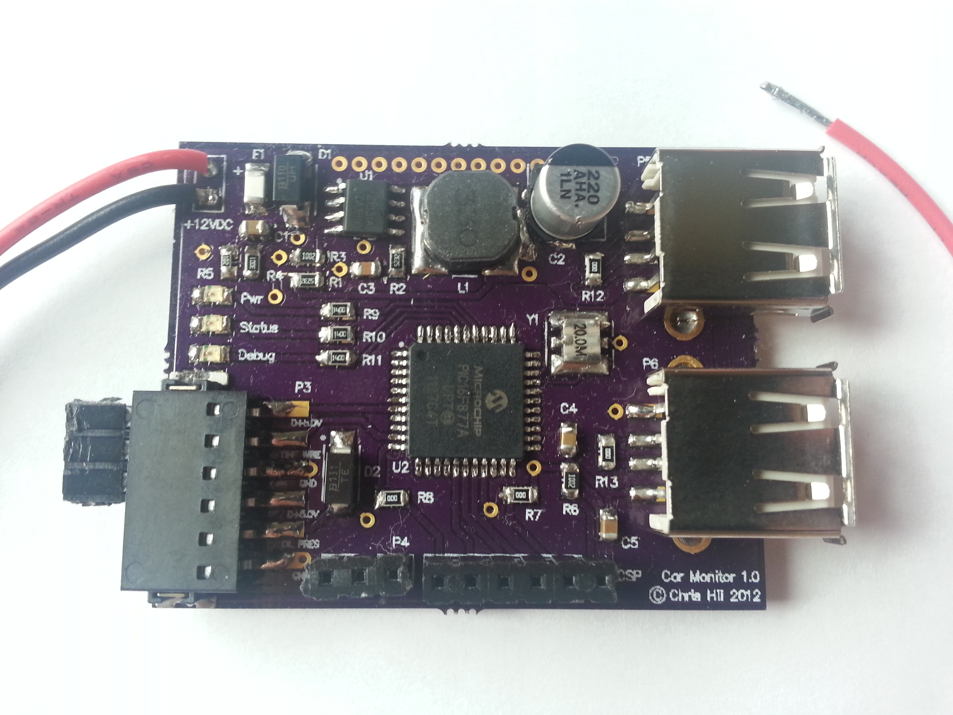
As a side note, please excuse the apparent lack of soldering aptitude on the board. I did this board using a backup soldering iron that would probably have been more suited to making joints in house plumbing.
Monitoring Choices
In aging vehicles the cooling system components are often prone to mechanical failures. For this reason, as well as some peace of mind during autocross events, I felt it was important to monitor the coolant temperature. The stock gauge cluster does have a coolant temperature gauge but its accuracy is reputedly very poor and serves only to inform you that the temperature has reached catastrophic levels when it is far too late. An accurate water temperature display was a must for this project.
Oil pressure is arguably the most critical engine parameter to monitor. The lack of adequate oil pressure usually indicates a severe internal engine problem and can lead to imminent engine destruction as well as the destruction of the turbocharger bearings. The car did not come with a stock oil pressure gauge; only a warning lamp that illuminated when the oil pressure was detected to be below 8 psi (0.55 bar). This too, like the stock coolant temperature gauge, generally only serves to inform you that your engine has been damaged. Therefore an accurate oil pressure display was also a must for this project.
The battery voltage is very easy to monitor and can indicate problems with the alternator, charging system or battery. Since it was also a low-hanging fruit, it was a no-brainer to add it to the project.
Goals
To keep things simple I decided on two very reasonable objectives:
- To accurately monitor several engine parameters, namely:
- Water temperature
- Oil pressure
- Battery voltage
- To display the measured values to the user via an LCD display mounted to the dashboard.
Sensors
There are a variety of sensors (also called senders) widely available from aftermarket tuning companies for relatively low cost. However, through experience in the past I know that many of the gauges provided have significant inaccuracies. Perhaps not significant enough to defeat the purpose of the gauge, but being an engineering student at the time I wanted to see if I could do better.
Water Temperature
 |
|---|
| Autometer 2253 |
Autometer 2253 - Resistive Temperature Sender
This is a resistive temperature sender with a not-very-linear output. When used as the lower resistor in a resistor divider, the output voltage can be made approximately linear for easier interpreting of the data. Its resistance varies from approximately 1.1 kΩ at about 38°C to 20 Ω at 170°C. I made a spreadsheet to calculate the corresponding values read by the microcontroller’s analog-to-digital converter (ADC):
 |
|---|
| Temperature to ADC value worksheet |
For the best water temperature measurements, I wanted the sender placed in the direct flow of coolant as close to the head as possible. To do this, I drilled out the bleed valve on the thermostat housing and retapped it for 1/8" NPT. This allowed me to monitor the coolant temperature even before the thermostat has opened (or if it has jammed shut).
Oil Pressure
 |
|---|
| Prosport Premium Pressure Sender |
Prosport Premium Pressure Sender
This is an analog, linear 0-5 V output sender with a range of 0-145 psi (0-10 bar).
The oil pressure sender required some adapters to couple with the motor as the sender uses 1/8-27 NPT threads whereas the motor uses BSPT threads. I installed it in parallel with the original low oil pressure switch using a tee fitting on the oil filter block.
Electrical Design
The electronics for the project consists mainly of a PIC16F877A microcontroller (datasheet) and supporting circuitry. The ADC is used to measure the outputs of the water temperature resistor divider and oil pressure sensors, as well as monitor the car’s battery voltage through another resistor divider. There is also a switching buck regulator supply based on an AOZ1031 (datasheet) capable of 3.0A output to supply the main 5.0V rail as well as rapid-charge up to two USB devices (two phones that is, not two power hungry iPads at 2.1A each).
The power input, sensor connections and status LEDs are placed on the left of the PCB. The microcontroller is placed in the center with the switching power supply above and the ICSP port and LCD connections below. Two USB-A receptacles are located on the right edge.
The circuit was initially made on a proto-board but eventually designed onto a PCB for a cleaner install into the car.
The schematics are available at the bottom of the page.
PCB Design
I designed the PCB to be mounted to a surface inside the center console, with the USB connectors flush with the face of the console and all components on the top side. This would remove the need for an enclosure and allow decent flexibility with the wire routing for the sensors.
The layout was completed on a 2.0" x 1.58", 2-layer PCB. I chose to go with 0805 components as this is a simple design and the minimum PCB size was mostly dictated by the I/O connectors anyways. Board manufacturing was done using OSHPark’s excellent PCB service - I highly recommend them. Their great service (including ENIG finish), low price and reasonable turnaround times impressed me.
The only layout dependent elements in this design were the buck supply and perhaps microcontroller resonator. For the buck supply, the high dI/dt loop area was minimized and plenty of heatsinking copper was attached to the pins of the regulator (which has the intregrated switching MOSFET). The resonator was placed very close to the microcontroller, but at 12 MHz this was not really critical.
 |
|---|
| Top side |
 |
|---|
| Bottom side |
Firmware
The firmware requirements were low enough that I didn’t bother using a simple OS or any sort of tasking architecture. The main loop simply cycles through the following steps:
- Read sensors
- Update variables
- Write to LCD
I wrote the firmware in C and compiled it for the 16F877A using the CC5X compiler. There’s not too much to say about the firmware, so I’ll let it speak for itself - I’ve attached the code at the bottom of the page.
Display
I chose a 4x16 LCD display with a piggyback microcontroller that accepted commands and data over a UART connection. This simplified the interface between the PCB and LCD to three wires: +5V, data and ground.
Unfortunately, I only managed to take a picture shortly after finishing the firmware but before installing in the vehicle. Here is a picture of how the LCD display looks during operation, with some bogus values from the missing sensors:
 |
|---|
| Engine monitor display without any sensors connected |
Results
The system was put into use after installing the sensors in the car and running the wires. It operated without any issues for a couple of days before encountering a failure where the system would hang and the microcontroller would stop running. After a bit of debugging, I found that installing a TVS (transient voltage suppression) diode at the 12V input was necessary to snub out any nasty spikes that occur on the vehicles power supply. No failures were experienced after that point and the system was in use for many months. It has been retired now as I’ve sold the car it was installed into, and my current car has an OBD-II system.